Biomass Turbine Generator,Biomass Silent Generator,Biomass Gas Generator Supermaly Generating Equipment Co., Ltd. , http://www.sdgenerating.com
The co-bottom insulation function is mainly achieved by maintaining the vacuum of the common bottom chamber. Under vacuum conditions, the thermal conductivity of air is negligible. Under normal temperature conditions, the vacuum at the bottom can reach 133Pa. When the low-temperature fuel is filled, the vacuum at the bottom can reach 1×10⁻² Pa at the liquid hydrogen temperature. However, if there is a leak at the bottom, it may cause hazardous gases to mix in the common bottom cavity and cause deflagration. In order to ensure the safety of the rocket, the pressure and hydrogen concentration of the common bottom should be monitored in real time during the low temperature fuel filling process.
2 System Design and Structure 2.1 System Structure and Principles The main functions of the hazardous gas monitoring system include: a) common bottom evacuation, leak detection and vacuum performance testing; b) real-time monitoring and alarm of common bottom pressure and hydrogen concentration during fuel refueling. The system structure is shown in Figure 1. 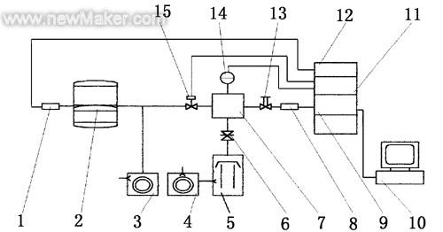
10-computer; 11-pressure control device; 12-β meter; 13-high vacuum valve; 14-ionization vacuum gauge; 15-vacuum crystal valve pumping through the 20m pipeline to the common bottom evacuation, under common temperature conditions under vacuum Degree can maintain 133Pa. The pressure measurement at the end of the joint was performed using a beta vacuum gauge, connected with a 30m cable and a beta gauge, and the pressure measurement range was 0.1 Pa to 5 kPa. A quadrupole mass spectrometer was used to measure the hydrogen concentration. The piezoelectric crystal valve was used to introduce a common bottom gas into the vacuum chamber. The mass spectrometer was separated according to the mass-to-charge ratio of the gas molecules, and passed to the computer in the form of mass spectrometry. The computer determined the gas composition based on the scanning voltage. Peak intensity calculates gas concentration. Since the high vacuum system provides the necessary working conditions for the mass spectrometer, the vacuum chamber ultimate pressure reaches 1×10⁻⁵Pa, the working pressure is maintained at 1×10⁻³Pa, and the pressure stability is 10%.
2.2 Design and calculation 2.2.1 Main technical specifications a) The distance between the pump and the common bottom of the system is approximately 18m, and the length of the air extraction pipe is not less than 20m. Starting from the atmospheric pressure condition, the total bottom pressure is less than 12h after the cumulative extraction time is 12h. 266Pa;
b) The common bottom pressure measurement range is 1×10⁻¹Pa to 1×10³Pa, and the measurement error is less than 15%;
c) The ultimate pressure of the vacuum chamber of the high vacuum system is 1×10⁻⁵Pa, the working pressure can be automatically controlled, maintained at 1×10⁻³Pa, and the pressure stability is 10%;
d) The mass spectrometer measures a mass range of 1.66×10⁻²⁷kg to 8.3×10⁻²⁶kg. The resolution is determined in units of 10% valleys. The concentration sensitivity to hydrogen detection is less than 1×10⁻⁴, and the measurement error is less than 10%. .
2.2.2 The design of the main components of the system The total limit pressure P can be calculated as follows P=Q/S
In the formula, Q--the ratio of common bottom leakage gas, Pa·m3/s;
S - the pumping speed of the common bottom, m3/s.
In general, the common bottom leak gassing rate is determined by the design and manufacturing process of the cryogenic tank. The pumping speed of the common bottom is limited by the conductance of the evacuated pipe. The length of the pipeline is determined by the evacuation distance of the rocket, so the design can only use the method of changing the diameter of the pipeline to change the conductance. The long pipe conductance under molecular flow can be calculated according to the formula in [1]. The conductance of a pipe with a length of 20m and a diameter of 1cm is approximately 6 x 10⁻⁶ m3/s. If you set the bottom leak gassing rate of 1×10⁻³ Pa·m3/s, you can calculate the ultimate pressure of the common bottom at 166Pa.
The mass spectrometer uses QMS064 quadrupole mass spectrometer. The mass range of the instrument is 1.66×10⁻²⁷kg~1.06×10⁻²⁵kg. Faraday cups were used as ion collectors, and the sensitivity of the instrument's detection concentration was 10-5. Using computer control and data processing, the instrument can simultaneously detect the concentration of several gases in the common bottom, and the change trends of various gas concentrations can be dynamically displayed. In order to achieve real-time monitoring of the entire process.
The design of a high vacuum system should take into account the system's ultimate vacuum availability, injection and work pressure stabilization, and reduce system contamination to the mass spectrometer. In order to obtain a high pumping speed for hydrogen, a diffusion pump is used as the main pump, pumping speed is greater than 0.1m3/s, and the limiting pressure is less than 1x10⁻⁶Pa. Liquid nitrogen traps can increase the vacuum of the system and reduce oil contamination. Installing a high-vacuum valve between the vacuum chamber and the mass spectrometer probe and properly selecting the operating procedures can effectively prevent oil contamination of the mass spectrometer probe.
Gas injection is performed using an automatic pressure control loop. The automatic pressure controller, ionization vacuum gauge, and piezoelectric crystal valve constitute a closed pressure control loop. The ionization vacuum gauge is a pressure sensing element. The pressure change in the vacuum chamber can cause the ion flow signal to change. The pressure controller compares the changed ion flow signal with the set value and gives a signal to control the piezoelectric crystal valve, which changes the flow of the valve. Guide to control the amount of gas sampled.
The pressure measurement of the common bottom first considers the safety of the measurement. For the measurement in the original position, the pressure gauge is directly connected with the common bottom box. In the case of a mixture of hydrogen and oxygen dangerous gases, the pressure gauge cannot have any heat source and cause the deflagration of the mixed gas. In this design, the beta-type ionization gauge is selected as the pressure gauge, and a small amount of radioactive emission from the radon source ionizes the gas to produce a weak ion current signal of 1×10⁻¹⁰A, ensuring the safety of measurement. The signal is transmitted to the measuring instrument through the 30m cable. The measuring instrument performs signal amplification and data processing. The pressure value and the change trend can be displayed at the same time, realizing the real-time monitoring of the common bottom pressure.
3 Test and Performance Test 3.1 Test System 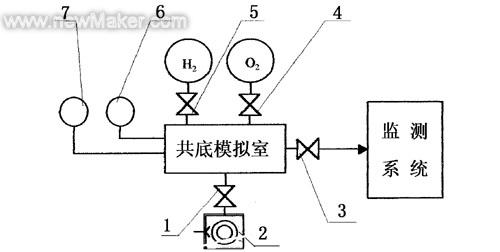
3.2 Performance index test In order to obtain the performance index of the test system, a test plan and operating rules for the common bottom safety monitoring system were prepared, and the system indicators were tested one by one according to the outline and operating rules. The test results are listed in Table 1. 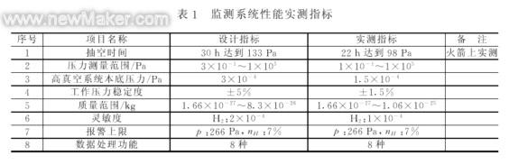
4 Application The Dangerous Gas Monitoring System has been successfully used for the launch test of the Long March Series III rocket. Many tests have proved that the system has stable performance, reliable quality, and rapid and accurate measurement data to ensure the safe launch of the rocket. Applications of the system include both the bottom-end vacuum performance test and the common bottom safety monitoring during the fueling process.
4.1 Common bottom vacuum performance test 4.1.1 Common bottom limit pressure measurement The common bottom limit pressure refers to the pressure that the common bottom meets the specified suction system and the total bottom at the pumping time specified in the operating rules. This indicator is a comprehensive indicator that reflects the total end-leakage gassing rate and pumping performance. When the common bottom leak gas vent rate is determined, the ultimate pressure of the common bottom depends mainly on the pumping speed of the pumping system. Therefore, when measuring this index, it is necessary to ensure the normal working conditions of the pumping system: the normal operation of the mechanical pump and the leakage of the suction pipe.
Since the method of intermittent evacuation is used for the common bottom, the best way to measure the ultimate pressure is to draw the curve of the relationship between the common pressure and the extraction time. According to the trend of the curve and at the specified time point, the corresponding pressure is found. For the measured value. Figure 3 shows a typical bottom draw curve. Due to the intermittent pumping, the co-bottom pressure is increased due to the outgassing of the co-bottom-cored FRP each time the suction is stopped. From the curve, the extraction time and ultimate pressure of the common bottom can be found out. 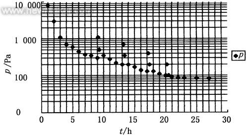
Figure 3: Typical co-bottom pumping curve â—† - Pressure 4.1.2 Measurement of leakage and gassing rate After stopping the pumping at the bottom, the pressure is changed by P = Qt/V, where Q is the total bottom leak gassing rate. Under normal conditions, the rate of deflation of the common base accounts for the major part. The deflation process is a slow process due to the restrictions of the co-bottom honeycomb sandwich flow conductance. Experiments show that this process takes several hours. In order to correctly measure the total end-leakage gassing rate, it must be selected long enough, usually 24 hours.
The total end-leakage rate test is only meaningful if the co-bottom pumping is performed long enough. In the initial period of co-bottom pumping (cumulative pumping time is less than 10h), due to the large amount of deflation of the common bottom, the measured data is difficult to correctly reflect the true state of the total bottom. According to a large number of experimental data of the common bottom leak gassing rate test, it is stipulated in the test procedure that after the total accumulated gas extraction time is 30 h, the total bottom leak rate is measured at room temperature for 24 h.
The test method is: close the common bottom box valve, record the pressure within a total of 24 hours, plot pressure and time curve, and calculate the total bottom leak gas release rate. If necessary, the leak rate and the gas release rate can be calculated separately.
4.2 Safety monitoring of the common bottom during fuel filling During the rocket's low-temperature fuel liquid hydrogen and liquid oxygen filling, the monitoring system monitors the common bottom pressure and hydrogen concentration in real time. Figure 4 shows the pressure and pressure in the case of no leakage at the common bottom during the filling process. Concentration change over time.
From the change curve, it can be seen that when the liquid hydrogen pre-cooling is completed, the pressure at the common bottom rapidly drops, and the pressure drops by 3 orders of magnitude in less than 2 minutes. This is due to the low temperature of the co-bottom surface at the liquid hydrogen temperature. Caused by co-bottom pumping. If the bottom does not leak, the pressure can be maintained at 1×10⁻¹Pa. The hydrogen concentration always fluctuates by 1% during the entire filling process. This value can be considered as the background of the vacuum system. 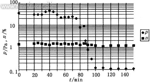
Fig. 4 Curve of pressure and concentration at the same time for liquid hydrogen and liquid oxygen filling process â—† Pressure; â– Hydrogen concentration During the filling process, if there is a leak, the pressure and concentration curves can change significantly, the pressure increases rapidly, and the gas concentration increases. The change can be changed according to the curve corresponding to different gases. When air leaks from the sealing tape into the common bottom, nitrogen and oxygen concentrations increase, and when the common bottom leaks, hydrogen concentration or oxygen concentration increases. The location of the leak can be determined based on the type of gas with increased concentration, and the amount of leakage can be determined based on the increase in concentration.
5 Conclusion The hazardous gas monitoring system uses mass spectrometry to monitor the dangerous gas in the rocket. After several tests of emission, the design of the system basically meets the requirements for use. With an atmospheric sampling device, the system can also be used for hazardous gas monitoring in the atmosphere. In order to expand the scope of application, the system can be further improved in improving detection sensitivity, reducing weight and volume, preventing or reducing pollution, and the like.
Wang Rongzong: Male, 58 years old, senior engineer, engaged in vacuum and mass spectrometry research, currently conducting space mass spectrometry measurements and spacecraft hazardous gas detection work Wang Rongzong (Lanzhou Institute of Physics, Lanzhou, 730000)
Sun Tianhui (Lanzhou Institute of Physics, Lanzhou, 730000)
References 1, Dao et al. Vacuum Design Manual. National Defense Industry Press, 1991.
Hazardous gas monitoring system design and characteristics
1 Introduction The three-stage propellant box of the Long March III launch vehicle is a cryogenic tank with a common bottom. The tank is divided into two separate parts: the liquid oxygen tank and the liquid hydrogen tank. The common bottom must not only bear the loads of the liquid hydrogen and liquid oxygen tanks working at the same time, but also bear the loads that may occur independently of each other. In addition, the co-bottom also needs to provide effective insulation to minimize heat transfer between the two tanks. Because hydrogen and oxygen have a risk of detonation under certain conditions, the total bottom is a safety barrier for both cabinets. Fig.1 Schematic diagram of hazardous gas monitoring system 1-β; 2-co-bottom; 3-vacuum pump; 4-foreline pump;5-diffusion pump; 6-gate valve; 7-vacuum chamber; 8-mass spectrometer probe ;9-Mass spectrometer; 1-4#valve;2-mechanical pump;3-3#valve;4-2#valve;5-1#valve;6-beta;7-HLP-03 gauge monitoring system performance test and some indicators The test is performed on an analog auxiliary system with a common bottom, and some special indicators are measured on the rocket. The structure of the auxiliary system is shown in Figure 2. The common-bottom simulation chamber is a low-vacuum chamber with a volume of V. Mechanical pumping can make the vacuum in the simulation chamber reach 0.1 Pa. Hydrogen and oxygen are respectively contained in the sample bottle. Gas is introduced into the simulation chamber through valves #1 and #2. The pressure can be measured with the HLP-3 gauge, and the mixed gas concentration can be calculated from the ratio of the measured partial pressures. The beta gauge and HLP-3 are placed in the same position in the simulation room. The simulation chamber mixture gas is connected to the monitoring system through a 3# valve.