Pressure transmitter wiring diagram: Pressure transmitter works: The piezoresistive type transmitter adopts a piezoresistive sensitive core body, which is small in size, high in sensitivity and good in stability. Its characteristics are mainly reflected in its sensitive core. As the name implies, the principle of a piezoresistive transmitter is that the sensitive core generates a resistance change after being pressurized, and then the amplifier circuit converts the resistance change into a standard signal output. The pressure transmitter measures the two pressures of the medium into the high and low pressure chambers. It acts on the isolating diaphragms on both sides of the δ element (ie, the sensitive element) and transmits it to the measuring film through the spacers and the filler fluid in the element. On both sides of the sheet. Measure the diaphragm and the electrodes on both sides of the insulating sheet to form a capacitor. IS Type Single-Stage Centrifugal Pump Single-Stage Centrifugal Pump,Horizontal Single-Stage Centrifugal Pump,Single-Stage Centrifugal Water Pump Shenyang pump products sales co., LTD , http://www.syipsc.com

When the pressures on both sides are inconsistent, the measuring diaphragm is displaced, and the displacement is proportional to the pressure difference. Therefore, the capacitance on both sides is not equal, and the signal is proportional to the pressure through the oscillation and demodulation steps. Pressure transmitters and absolute pressure transmitters work in the same way as differential pressure transmitters, except that the low pressure chamber pressure is atmospheric or vacuum.
The A/D converter converts the demodulator current into a digital signal whose value is used by the microprocessor to determine the input pressure value. The microprocessor controls the operation of the transmitter. In addition, it performs sensor linearization. Reset the measurement range. Engineering unit conversion, damping, square root, and sensor trimming operations, as well as diagnostics and digital communications.
The microprocessor has a 16-byte program RAM and three 16-bit counters, one of which performs A/D conversion.
The D/A converter fine-tunes data from the microprocessor and the corrected digital signal, which can be modified by the transmitter software. The data is stored in the EEPROM and remains intact even if the power is turned off.
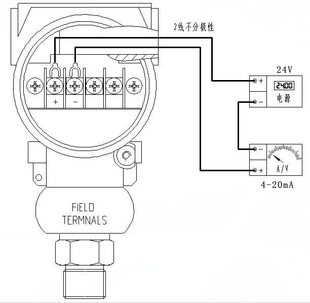
The digital communication line provides the transmitter with a connection interface to an external device (such as the Model 275 smart communicator or a control system using the HART protocol). This line detects the digital signal superimposed on the 4-20mA signal and transmits the desired information through the loop. The type of communication is frequency shift keying FSK technology and is based on the BeII202 standard.